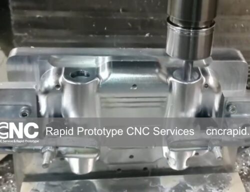

When light has only a few microns of wiggle room before image quality degrades, every mechanical interface around an optic must be machined with the same rigor as the lens itself. Modern CNC milling and turning—augmented by diamond‑turning and ultraprecision polishing—give optical designers the repeatable, sub‑10 µm accuracy they need without slow, hard‑to‑scale manual fitting. At CNC Rapid we routinely cut parts for lidar assemblies, machine‑vision cameras, laboratory spectrometers, and even small satellite payloads, so the lessons below come straight from the shop floor.
Why CNC Machining Remains the Optics Workhorse
| Benefit | Typical Tolerance |
| Tight, predictable tolerances | ±0.005 mm bores keep lenses coaxial, reducing coma and astigmatism. |
| High surface integrity | Single‑point diamond turning yields <15 nm Ra on mirrors—no extra polishing passes. |
| Geometric flexibility | 5‑axis milling slashes weight by pocketing mirror cells and baffles without sacrificing stiffness. |
| Rapid iteration | Fixtures are programmed, not hand‑built, so engineers can tweak a mount and see metal in days. |
Common Materials—and Why They Matter
| Material | Typical Optical Use | Notes |
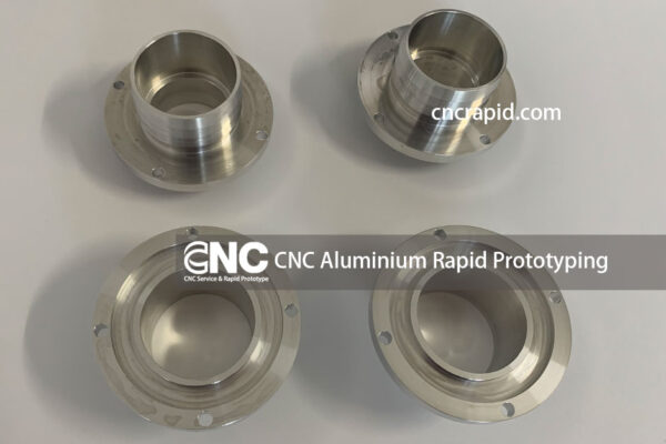
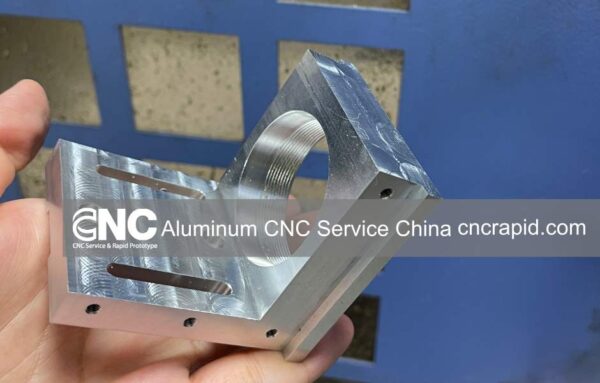
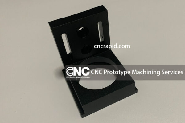
| 6061‑T6 Aluminum | Lens barrels, sensor housings | Light, stable, black‑anodizes well for stray‑light suppression. |
| 7075‑T651 Aluminum | High‑stiffness mirror cells | 30 % higher modulus than 6061, holds thread strength for repeated optics swaps. |
| Stainless 304/316 | Vacuum chambers, cryogenic benches | Non‑magnetic, corrosion‑resistant; electropolish for 0.2 µm Ra. |
| Invar 36 | Space‑borne optical benches | CTE ≈ 1.2 µm/m‑°C keeps alignments intact through –40 °C to +60 °C. |
| Copper & Cu‑Alloys | Laser pump cavities | Excellent thermal conductivity for steady wavefronts. |
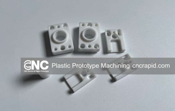
| Black POM (Acetal) | Lightweight filter wheels | Dampens vibration, machines chip‑free at high feed rates. |
Tolerances & Surface Finish: Where the Numbers Really Count
Bore concentricity: 0.01 mm TIR between lens steps eliminates tilt that can introduce spherical aberration.
Flatness on reference faces: ≤ 0.005 mm across 100 mm ensures mirrors bond without stress.

Surface roughness:
- Reflective mirrors: <15 nm Ra via diamond turning.
- Mechanical mating surfaces: 0.4 µm Ra is sufficient; going smoother adds cost without optical benefit.
Stress relief: Pre‑machining aging or cryo‑cycling stabilizes aluminum so bores don’t “creep” out of spec over time.
Design Tips for Optical Engineers
- Add locating shoulders instead of relying solely on thread engagement; this shortens assembly time and boosts repeatability.
- Specify GD&T clearly—especially position and runout—so machinists know which datum controls wavefront alignment.
- Maintain uniform wall thickness (> 1.5 mm for aluminum) to prevent distortion during black anodizing or nickel plating.
- Leave 0.02 mm of stock on mirror seats if you plan a post‑machining lapping or polishing step.
- Avoid blind razor‑thin slots: Deep, narrow optical baffle slots trap chips and are hard to inspect; break them into stepped pockets instead.
Typical Optical Components We Machine
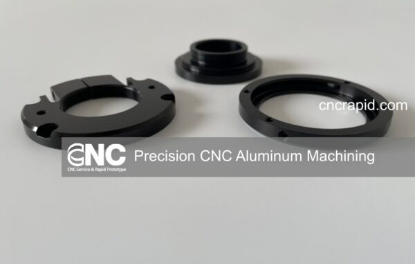
- Precision lens barrels with matched retaining rings
- Mirror cells and lightweighted back‑plates
- Prism mounts with angular adjustment slots
- Optical breadboard inserts and dowel‑pin reference plates
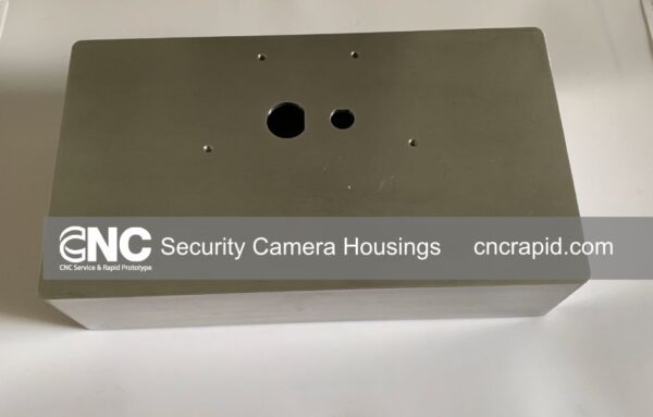
- Sensor enclosures for CMOS and InGaAs detectors
- Custom aperture stops and stray‑light baffles
(See our earlier post on “Black Anodized Camera Housings” for a deep dive into finish choices.)
Post‑Machining Finishes That Protect—and Perform
| Finish | Key Benefit | Application Note |
| Black Type II anodizing | 0.012–0.018 mm build; 3 % reflectance in VIS | Ideal for internal baffles & lens barrels. |
| Hard Type III anodizing | 0.025–0.050 mm build; wear‑resistant | Sliding dovetails and adjustment tracks. |
| Electroless nickel (EN) | 0.005–0.010 mm uniform layer | Corrosion barrier on stainless or copper optics. |
| Chemical conversion (Alodine 1200) | Virtually zero build | Conductive coating on PCB‑mounted optics. |
Optical systems live or die by microns. CNC machining—pairing rigid fixtures, high‑speed spindles, and ultraprecise inspection—remains the surest way to lock mechanical tolerances in step with optical performance. Whether you’re prototyping a custom spectrometer or ramping up production on drone‑borne lidar, CNC Rapid can turn your CAD into components that let the photons do their job.
Contact CNC Rapid Today
We invite you to take advantage of our Metal & Plastic parts machining service, ideal for both prototypes and production needs. To receive a personalized quote, simply visit our website to get quote or reach out directly to our team at [email protected] with details of your project.
For the most accurate and speedy quote, kindly include the following in your communication:
- Part Name
- 3D Drawing
- Quantity
- Material
- Tolerance Range
- Surface Finish
We appreciate your interest and look forward to serving your machining needs. Thank you for your time!