1. Structural characteristics and technical requirements of general shaft parts
General shaft parts are divided into four categories according to their structural characteristics: light shafts, stepped shafts, hollow shafts and shaped shafts (including crankshafts, half shafts, camshafts, eccentric shafts, cross shafts and splined shafts, etc). If the ratio of the length and diameter of the shaft (L / d) to be divided, and can be divided into rigid shafts (L / d ≤ 12) and flexible shafts (L / d ≥ 12) two categories.
a. Structural characteristics of general Shaft parts are rotating body parts, the length is greater than their diameter, and are usually composed of external cylindrical surfaces, tapered surfaces, threads, splines, keyways, transverse holes, grooves and other surfaces.
b. Technical requirements for general shaft parts
- Dimensional tolerances Shaft parts of the main surface is often divided into two categories: one is with the inner ring of the bearing with the outer journals, namely the bearing journal, used to determine the position of the shaft and support the shaft, the dimensional tolerance level required higher, usually IT5 ~ IT7; another class with various types of transmission parts with the journal, namely with the journal, its tolerance level is slightly lower, often IT6 ~ IT9.
- Geometric tolerances include shape tolerance, orientation tolerance, position tolerance and runout tolerance.
- Shape tolerance mainly refers to the roundness tolerance and cylindricity tolerance of important surfaces such as journal surface, outer conical surface, and taper hole. The error shall generally be limited to the dimensional tolerance; for precision shafts, the shape tolerance shall be specified separately on the part drawing.
- Directional tolerances refer to the tolerance of perpendicularity of the important end faces to the axis, the tolerance of parallelism between the end faces, etc.
- The positional tolerances refer to the tolerances of the inner and outer surfaces, the coaxiality of important axis surfaces, etc.
- The runout tolerance mainly refers to the radial runout tolerance of inner and outer surfaces, important shaft surfaces, etc.
- Surface roughness The machined surfaces of shafts have surface roughness requirements, which are generally determined by machining possibilities and economy. The surface roughness of the bearing journals is often Ra0. 2 to 1. 6 μm, and that of the mating journals of the transmission parts is Ra0. 4 to 3. 2 μm.
2. Machining process analysis and selection of positioning datum for general shaft parts
a. Machining process analysis of general shaft parts. For parts with high accuracy requirements, the rough and finish machining should be separated to ensure the quality of the parts. Shaft parts processing can generally be divided into three stages: rough turning (rough turning of the outer circle, drilling the center hole, etc.), semifinish turning (semi-finish turning of the outer circle, step and repair the center hole and secondary surface, etc.), rough and fine grinding (rough and fine grinding of the outer circle) . Each stage is roughly defined by the heat treatment process.
b. Selection of positioning datum for general shaft parts. The most common positioning reference for general shaft parts is the two center holes. Because the shaft parts of the outer surface, thread surface coaxially and end face perpendicularity of the axis is the main item of geometric tolerance, and the design reference of these surfaces are generally the centerline of the shaft, the use of two center hole positioning can comply with the principle of coincidence of the reference; and because most processes use the center hole as the positioning base, can maximize the processing of multiple outer and end faces, which is also consistent with the principle of unity of the reference. However, two center holes cannot be used as a datum in the following cases.
- When roughing the outer circle, in order to improve the rigidity of the workpiece, the surface of the outer circle of the shaft is used as the positioning base, or the outer circle and the center hole are used as the positioning base, i.e. one clamping and one top.
- When the shaft is a through-hole part, the center hole, which is the locating surface, disappears during machining due to the drilling of the through-hole, and in order to use the center hole as the locating surface after the through-hole has been machined, three methods are often used.
- When the diameter of the central hole is small, a 60° inner taper with a width of not more than 2 mm can be directly inverted at the hole instead of the central hole.
- When the shaft has a cylindrical hole, a tapered plug can be used with a taper of 1:500. When the taper of the shaft hole is small, the taper of the plug is the same as the taper of the positioning holes at both ends of the workpiece.
- If the shaft bore is tapered and the taper of the shaft through-hole is large, a mandrel with a tapered plug, referred to as a tapered plug mandrel, may be used.
When using tapered plugs or tapered plug arbors, care should be taken not to replace or disassemble them until the center bore is no longer in use after finishing each machined surface.
3. Materials and heat treatment of general shaft parts
a. Materials and blanks for general shaft parts
- General shaft parts materials commonly used 45 steel, high precision shaft can be selected 40Cr, GCr15, 65Mn, can also choose ductile iron; high-speed, heavy-duty shaft, choose 20CrMnTi, 20Mn2B, 20Cr and other carburized steel or 38CrMoAl nitriding steel.
- Commonly used billets for general shaft parts are round bars and forgings; large shafts or shafts with complex structures use Casting. After heating and forging, the billet can be heated so that the internal fibers of the metal are evenly distributed along the surface, resulting in high tensile strength, bending strength and torsional strength.
b. Heat treatment of general shaft parts
- Forging blanks before processing, are required to arrange normalizing or annealing treatment, so that the internal grain refinement of steel, eliminate forging stress, reduce material hardness, improve machinability.
- Tempering is generally arranged after rough turning and before semi-finishing turning to obtain good overall mechanical properties.
- Surface hardening is usually scheduled prior to finishing to correct local distortion caused by hardening.
- Shafts with precision requirements must also be subjected to low-temperature aging after partial hardening or rough grinding.
4. Example of machining a general shaft part
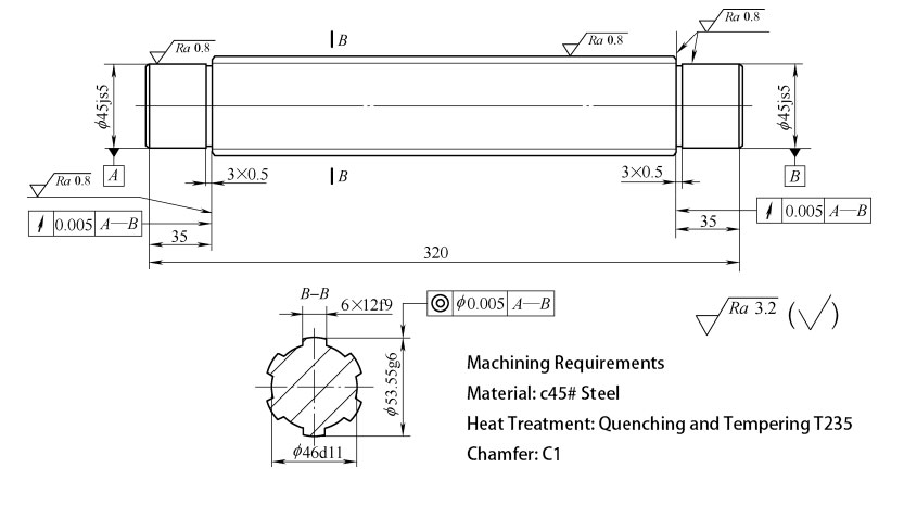
Example 1: Spline shaft

Spline Shaft
a. Part drawing analysis
- The spline shaft shown in above is based on the common axis of the two journals ϕ45js5, the coaxial tolerance of ϕ53. 55g6 to the datum is ϕ0. 005 mm, and the axial runout tolerance of the two ϕ53. 55g6 end faces to the datum is 0. 005 mm.
- Part material is 45 steel.
- Tempered to a hardness of 220 to 250 HBW.
b. Process Analysis
- The part is a splined shaft and the centering method is OD centering.
- In the machining process, the roughing process is followed by overall tempering and then finishing.
- In single piece or small batch production, horizontal lathe is used, rough and finish turning can be done on one lathe; in larger batch, rough and finish turning should be done on different lathes.
- ϕ 45 js5 and ϕ53.55g6 have high cylindrical accuracy, so the finish turning process leaves a grinding allowance and the final grinding is done with a cylindrical grinder.
- In order to ensure concentric center bores at both ends, the center bore of the shaft is initially used only as a temporary center bore; finally, during finishing, the center bore is reworked or ground and then positioned with the finished center bore.
c. Machining Processes (see Table, Unit: mm)
| Name of Parts | Type of material | Material | Type of production |
|---|---|---|---|
| spline shaft | round steel | C45# steel | small batch |
| working procedure | working step | Work Content | Equipment | Tools, gauges, auxiliaries |
|---|---|---|---|---|
| 10 | Downstream ϕ60×325 | sawmill | ||
| 20 | roughing | Horizontal lathe | ||
| 1 | Clamp the outer circle of the blank, turn the end face and see the light. | 45° elbow turning tool | ||
| 2 | Drilling of a central hole at one end A2.5 / 5.3 | center drill | ||
| 3 | Turn the head, clamp the outer circle of the blank, turn the end face and ensure the total length 322 | 45° elbow turning tool | ||
| 4 | Drill the center hole of the other end A2.5 / 5.3 | center drill | ||
| 5 | Clamp the left outer circle of the blank and use the center hole of the other end with the top of the center, rough turning ϕ45js5. Outer circle to ϕ47, length to 35 | 90° external turning tool | ||
| 6 | Turn ϕ53.55g6 cylindrical to ϕ56 | 90° external turning too | ||
| 7 | Turn the head. Clamp ϕ45js5 at the outer circle with a self-centering chuck, and at the other end, clamp the center hole with a centering tip, and turn ϕ45js5 to ϕ47 at the outer circle and 35 at the length. | 90° external turning tool | ||
| 30 | Heat treatment: tempered, hardness 220 to 250 HBW | chamber furnace | ||
| 40 | fine turning | Horizontal lathe | ||
| 1 | Clamp with self-centering chuck ϕ45js5 on the outer circle, the other end is clamped with the center hole by the centering tip, and a section is turned on ϕ53.55g6 on the outer circle with surface roughness Ra3.2μm |
90° external turning tool | ||
| 2 | Attach the center frame at the ϕ53.55g6 outer frame position, square it up and remove the center. Turn the end face to ensure that the total length 321 | 45° elbow turning tool | ||
| 3 | Repair center hole to A3.15 / 6.7 | center drill | ||
| 4 | Turn the head, clamp ϕ45js5 on the outer circle with a self-centering chuck, clamp the other end with the center hole with a centering pin, mount the centering pin at ϕ53.55g6, square it up and remove the centering pin. Turn the end face to ensure a total length of 320 mm. | 45° elbow turning tool | ||
| 5 | Repair center hole to A3.15 / 6.7 | center drill | ||
| 6 | Hold the center hole, clamp, remove the center frame, turn ϕ45js5 and leave the grinding allowance for the outer circle 0.25, growing to 35 | 90° external turning tool | ||
| 7 | Turn ϕ53.55g6 cylindrical, leaving a grinding allowance of 0.25 | 90° external turning tool | ||
| 8 | turning 35 size, left side grinding allowance 0.10 | 45° elbow turning tool | ||
| 9 | milling 3 x 0.5 retracting slots to the required | Groove cutter | ||
| 10 | External chamfering C1 | 45° elbow turning tool | ||
| 11 | Turn the head, clamp ϕ45js5 outer circle with self-centering chuck, clamp the other end with the center hole with a centering tip, turn ϕ45js5, leaving a grinding allowance of 0.25 | 45° elbow turning tool | ||
| 12 | Turning 35 size, right side grinding allowance 0.10 | 45° elbow turning tool | ||
| 13 | Cut 3 x 0.5 retracting slots to the required | Groove cutter | ||
| 14 | External chamfering C1 | 45° elbow turning tool | ||
| 50 | Milling external spline to drawing requirements | Vertical Machining Center | ||
| 60 | Clamp deburring | bench | ||
| 70 | Grind both end center holes | Center Hole Grinder | ||
| 80 | cylindrical grinding | Cylindrical grinding machines | ||
| 1 | Grind left end ϕ45js5 cylindrical to requirement, surface roughness Ra0. 8μm | |||
| 2 | Grinding against 35 dimensions right side up to required, surface roughness Ra0. 8μm | |||
| 3 | Grind right end ϕ45js5 cylindrical to requirement, surface roughness Ra0. 8μm | |||
| 4 | Lean grinding 35 Dimensions left side to required, surface roughness Ra0. 8μm | |||
| 5 | Grinding ϕ53. 55g6 Outer circle to requirement, surface roughness Ra0. 8μm | |||
| 90 | Inspection: Inspection of dimensions, geometric tolerances and surface roughness of each part, etc | testing lab | ||
| 100 | Oiling, packaging, storage | in stock |
Example 2: Shaft
Shaft
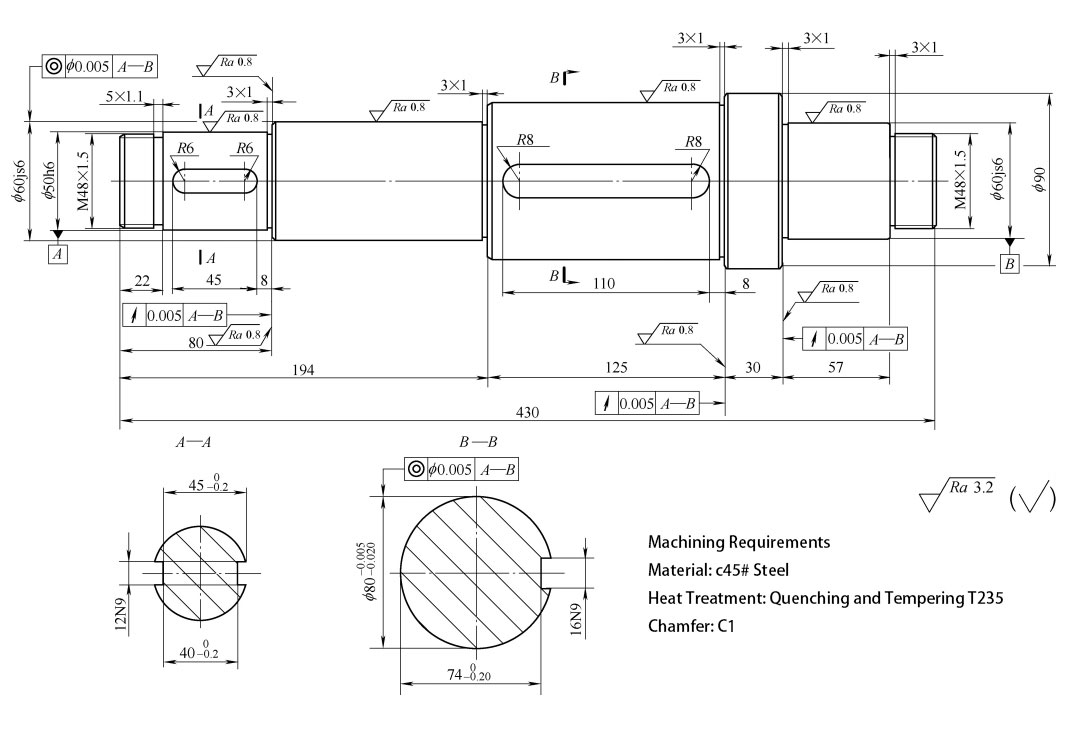
a. Part drawing analysis
- The shaft shown in the above picture is based on the common Shaft of the journals ϕ50h6 and ϕ60js6 at the right end. The tolerance of the coaxiality of the outer circle ϕ80-0. 005 mm and the outer circle ϕ60js6 (middle position) to the datum is 0. 005 mm.
- The material of the part is 45 steel.
- Tempered hardness of 220 to 250 HBW.
b. Process Analysis
- During the machining process, the roughing process is followed by an overall tempering process and then a finishing process.
- In single piece or small batch production, using ordinary lathe, rough and finish turning can be done on one lathe; in larger batch, rough and finish turning should be done on different lathes.
- ϕ80(-0.005 -0.020) mm cylinders, ϕ60js6 cylinders and ϕ50h6 cylinders with high accuracy requirements are left for grinding in the finishing process and finally ground with a cylindrical grinder.
- In order to ensure concentric center bores at both ends, t h e shaft center bore is initially used only as a temporary center bore. Finally, during finishing, the center bore is reworked or ground and then positioned with the finished center bore.
c. Machining Processes (see Table, Unit: mm)
| Name of Parts | Type of material | Material | Type of production |
|---|---|---|---|
| Shaft | round steel | C45# steel | small batch |
| working procedure | working step | Work Content | Equipment | Tools, gauges, auxiliaries |
|---|---|---|---|---|
| 10 | Downstream ϕ100 x 435 | sawmill | ||
| 20 | roughing | Horizontal lathe | ||
| 1 | Clamp the outer circle of the blank, turn the end face and see the light. | 45° elbow turning tool | ||
| 2 | Drilling of one end of the central hole A3. 15 / 6. 7 | center drill | ||
| 3 | Turn the head, clamp the outer circle of the blank, turn the end face and ensure the total length 432 | 45° elbow turning tool | ||
| 4 | Drill the center hole of the other end A3.15 / 6.7 | center drill | ||
| 5 | Clamp the outer circle of the left end of the blank and use the center hole of the other end to hold the center hole. Outer circle to ϕ50, length to 24 | 90° external turning tool | ||
| 6 | Turn ϕ60js6 OD to ϕ62, length to 57 | 90° external turning too | ||
| 7 | Turning ϕ90 cylindrical to ϕ92, length to 32 | 90° external turning tool | ||
| 8 | Turning ϕ80(-0. 005 -0.020) Outer circle to ϕ82, length to 125 | 90° external turning tool | ||
| 9 | Turn the head. Clamp M48 x 1.5 at the outer circle with a self-centering chuck and the other end against the center hole with a centering tip, clamp, turn M48 x 1.5 outer circle to ϕ50, length to 22 | 90° external turning tool | ||
| 10 | Turn ϕ50h6 OD to ϕ52, length to 58 | 90° external turning tool | ||
| 11 | Turn ϕ60js6 OD to ϕ62, length to 114 | 90° external turning tool | ||
| 30 | Heat treatment: tempered, hardness 220 to 250 HBW | chamber furnace | ||
| 40 | fine turning | CNC Lathe | ||
| 1 | Clamp with self-centering chuck M48 x 1.5 at the outer circle, use the other end to hold the center hole with the top, clamp, and turn a section of the ϕ60js6 outer circle to a surface roughness of Ra3.2μm | 35° Machine Clamped Blades | ||
| 2 | Attach the center frame to the ϕ60js6 outer frame, square it up and remove the center. Turn the end face to ensure the total length 431 | 35° Machine Clamped Blades | ||
| 3 | Repair center hole to A4 / 8.5 | center drill | ||
| 4 | Turn the head, clamp the M48 x 1.5 outer ring with a self-centering chuck, use the other end to hold the center hole with a center, clamp it, mount the center frame on the outer ring position ϕ60js6, square it up and remove the center. Turn the end face to ensure a total length of 430 mm. | 35° Machine Clamped Blades | ||
| 5 | Repair center hole to A4 / 8.5 | center drill | ||
| 6 | Hold the center hole, clamp it, remove the center frame, and turn the M48×1.5 thread | Threaded Turning Tools | ||
| 7 | Turn ϕ50h6 cylindrical, leaving a grinding allowance of 0.25 | 35° Machine Clamped Blades | ||
| 8 | Turn ϕ60js6 cylindrical, leaving a grinding allowance of 0.25 | 35° Machine Clamped Blades | ||
| 9 | Turning ϕ80(-0. 005 -0.020) cylindrical, leaving a grinding allowance of 0.25 | 35° Machine Clamped Blades | ||
| 10 | Turning 80 size, right side grinding allowance 0.10 | 35° Machine Clamped Blades | ||
| 11 | Turning 194 Dimensions into | 35° Machine Clamped Blades | ||
| 12 | Turning 125 size, right side grinding allowance 0.10 | 35° Machine Clamped Blades | ||
| 13 | Turn 5 x 1.1 rewind slots to required | Groove cutter | ||
| 14 | Cut a 3 x 1 retracting slot to the requirement | Groove cutter | ||
| 15 | External chamfering C1 | 35° Machine Clamped Blades | ||
| 16 | Milling 2 x 12N9 keyway to requirement, surface roughness Ra3.2μm | Keyway milling cutter | ||
| 17 | Milling 16N9 keyway to requirement, surface roughness Ra3.2μm | Keyway milling cutter | ||
| 18 | Turn the head, use the self-centering chuck to clamp the M48 × 1.5 outer circle, use the other end to hold the center hole with the center, clamp it, and turn the M48 × 1.5 thread | Threaded Turning Tools | ||
| 19 | Turn ϕ60js6 cylindrical, leaving a grinding allowance of 0.25 | 35° Machine Clamped Blade | ||
| 20 | Turning ϕ90 cylindrical to requirement, surface roughness Ra3.2μm | testing station | 35° Machine Clamped Blade | |
| 21 | Turn 57 Dimensions right side up, surface roughness Ra3. 2μm | storeroom | 35° Machine Clamped Blade | |
| 22 | Turning 57 size, left side grinding allowance 0.10 | 35° Machine Clamped Blade | ||
| 23 | Cut a 3 x 1 retracting slot to the requirement | Groove cutter | ||
| 24 | External chamfering C1 | 35° Machine Clamped Blade | ||
| 50 | Grind both end center holes | Center Hole Grinder | ||
| 60 | Grinding outer circle and end face | Cylindrical grinding machines | ||
| 1 | Grinding ϕ50h6 cylindrical to the required surface roughness Ra0.8μm | |||
| 2 | Grind left end ϕ60js6 cylindrical to requirement, surface roughness Ra0. 8μm | |||
| 3 | Grinding ϕ80(-0. 005 -0.020) cylindrical to the required surface roughness Ra0.8μm | |||
| 4 | Against grinding 80 dimensions right side up to required, surface roughness Ra0. 8μm | |||
| 5 | Grinding against 125 dimensions right side up to required, surface roughness Ra0. 8μm | |||
| 6 | Turning, grinding right end ϕ60js6 cylindrical to required, surface roughness Ra0. 8μm | |||
| 7 | Lean grinding 57 Dimensions left side to required, surface roughness Ra0.8μm | |||
| 70 | Inspection: Inspection of dimensions, geometric tolerances and surface roughness of each part, etc. | testing lab | ||
| 80 | Oiling, packaging, warehousing | in stock |
Example 3: Eccentric Shaft
Eccentric Shaft
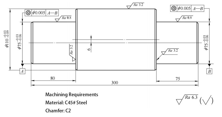
a. Part drawing analysis
- The eccentric shaft shown in above is based on the common Shaft of the two journals of the outer circle of ϕ75(-0.03 -0.06) mm.
- Part material is 45 steel.
b. Process Analysis
- The part is an eccentric shaft, ϕ110 (-0.03 -0.09) mm outer circle and ϕ75 (-0.03 -0.06) mm outer circle of the common shaft of both journals to ensure an eccentricity of 6 mm, two central holes should be machined on the left and right sides of the part: one centered on the ϕ75 mm outer axis and the other centered on the ϕ110 mm outer axis.
- In single piece or small batch production, using ordinary lathe, rough and finish turning can be done on one lathe; in larger batch, rough and finish turning should be done on different lathes.
- ϕ75 (-0.03 -0.06) mm with high cylindrical accuracy, with grinding allowance for the finishing process and finally with the cylindrical grinding machine to grind.
c. Machining Processes (see Table, Unit: mm)
| Name of Parts | Type of material | Material | Type of production |
|---|---|---|---|
| Eccentric Shaft | round steel | C45# steel | small batch |
| working procedure | working step | Work Content | Equipment | Tools, gauges, auxiliaries |
|---|---|---|---|---|
| 10 | Downstream ϕ120×305 | sawmill | ||
| 20 | Milling both end faces to ensure a total length of 300, drilling center and off-center holes | Horizontal machining center | ||
| 30 | Turn ϕ110 Outer circle | CNC Lathe | ||
| 1 | Clamp one end of the outer circle of the blank and the other end with the center hole with the center, clamp, rough turn ϕ110 Outer circle to ϕ111, long to jaws | 35° Machine Clamped Blades | ||
| 2 | Fine -turning ϕ110 rounded to requirements, long to jaws, rough surface Degree Ra3. 2μm | 35° Machine Clamped Blades | ||
| 40 | Turning ϕ75 Rounding, facing, chamfering | CNC Lathe | ||
| 1 | Attach the dial, use the tops at both ends to hold the eccentric center hole, with the unmachined end of the workpiece outside, and attach the chicken center chuck to the machined outer end, and use the dial to drive the chicken center chuck and The workpiece is rotated, counterweighted in the symmetrical direction of the eccentricity, and rough turned ϕ75 cylindrical to ϕ76, length 74.5 | 35° Machine Clamped Blades | ||
| 2 | Fine-turning ϕ75 cylindrical, leaving a grinding allowance of 0.50, length 74.5 | 35° Machine Clamped Blades | ||
| 3 | Turning ϕ110 end face to requirements, guaranteed size 75, rough surface Degree Ra3. 2μm | 35° Machine Clamped Blades | ||
| 4 | Turn ϕ75 External chamfering C2 | chamber furnace | 35° Machine Clamped Blades | |
| 5 | Turning, clamping method as above. Rough turning of ϕ75 external circle to ϕ76, length 79.5 | Horizontal lathe | 35° Machine Clamped Blades | |
| 6 | Fine-turning ϕ75 cylindrical, leaving a grinding allowance of 0.05, length 79.5 | 35° Machine Clamped Blades | ||
| 7 | Turning ϕ110 end face to requirements, guaranteed size 80, rough surface Degree Ra3. 2μm | 35° Machine Clamped Blades | ||
| 8 | Turn ϕ75 External chamfering C2 | 35° Machine Clamped Blades | ||
| 9 | Reassemble with the center hole pinned on both ends by the tops; place the cocking collet on the ϕ75 outer end, rotating the cocking collet and workpiece with a dial, ϕ 110 Chamfering of the outer ends C2 | 35° Machine Clamped Blades | ||
| 50 | Grinding ϕ75 cylindrical (2 places) to the required surface roughness Ra0.8μm | Cylindrical grinding machines | ||
| 60 | examine | testing lab | ||
| 70 | Oiling, packaging |
Example 4: Motor shaft
Motor Shaft
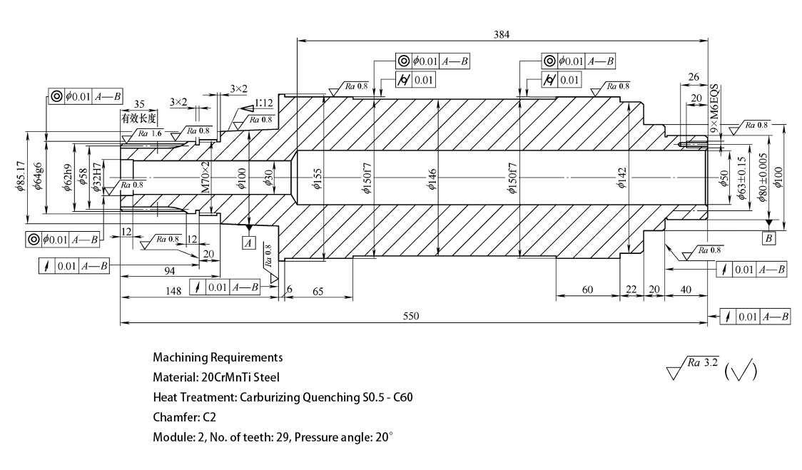
a. Part drawing analysis
- The motor shaft shown in above is based on the common Shaft of the two journals with 1:12 tapered circle and ϕ80 mm ± 0. 005 mm outer circle.
- The part material is 20CrMnTi steel.
- The depth of the carburized layer is 0. 5 to 0. 8 mm, and the hardness is 60 to 65 HRC after quenching and tempering
b. Process Analysis
- The dimensional and geometric tolerances and surface quality of the 1:12 tapered circle, ϕ80mm ± 0.005mm outer circle, ϕ64g6 outer circle and ϕ150f7 outer circle are very high.
- The gears are machined after finishing, using a self-centering chuck ϕ80 mm ± 0.5 mm. 0.005 mm OD, squared ϕ64g6 OD.
- In single piece or small batch production, using ordinary lathe, rough and finish turning can be done on one lathe; in larger batch, rough and finish turning should be done on different lathes.
c. Machining Processes (see Table, Unit: mm)
| Name of Parts | Type of material | Material | Type of production |
|---|---|---|---|
| Motor Shaft | round steel | 20CrMnTi steel | small batch |
| working procedure | working step | Work Content | equipment | Tools, gauges, auxiliaries |
|---|---|---|---|---|
| 10 | Drilling: self scribing, drilling center hole at one end A3. 15 / 6. 7 | drilling machine | center drill | |
| 20 | roughing | Horizontal lathe | ||
| 1 | Clamp the outer end of the blank with a self-centering chuck and clamp the other end with a center, turn ϕ80 ± 0.005 to ϕ82 | 90° external turning tool | ||
| 2 | Turning ϕ100 outer circle to ϕ102 | 90° external turning tool | ||
| 3 | Turn ϕ142 OD to ϕ144 | 90° external turning tool | ||
| 4 | Turning ϕ150f7 to ϕ152 | 90° external turning tool | ||
| 5 | Turning ϕ146 to ϕ152 | 90° external turning tool | ||
| 6 | Turn ϕ155 OD to ϕ157 | 90° external turning tool | ||
| 7 | Clamp with self-centering chuck ϕ80 ± 0.005 OD, square, clamp, turn end face. Total guaranteed length 552 | 45° elbow turning tool | ||
| 8 | Turn ϕ62h9 cylindrical to ϕ66 | 90° external turning tool | ||
| 9 | Turn ϕ64g6 cylindrical to ϕ66 | 90° external turning tool | ||
| 10 | Turn M70×2 threaded outer circle to ϕ76 | 90° external turning tool | ||
| 11 | Turn 1:12 taper to ϕ103 | 90° external turning tool | ||
| 30 | fine turning | CNC lathe | ||
| 1 | Clamp left end, top right end. Turn ϕ80 ± 0.005 cylindrical, leaving a grinding allowance of 0.8 mm. | 35° Machine Clamped Blades | ||
| 2 | Turn 40 size, left side grinding allowance 0.20 | 35° Machine Clamped Blades | ||
| 3 | Turning ϕ100 Outer circle to requirement, length 20, surface roughness Ra3. 2μm | 35° Machine Clamped Blades | ||
| 4 | Turning ϕ142 Outer circle to requirements, length 22, surface roughness Ra3. 2μm | 35° Machine Clamped Blades | ||
| 5 | Turning ϕ150f7 cylindrical, leaving a grinding allowance of 0.50 | 35° Machine Clamped Blades | ||
| 6 | Turning ϕ146 Outer circle to requirement, surface roughness Ra3.2μm | 35° Machine Clamped Blades | ||
| 7 | Turning ϕ155 Outer circle to requirement, surface roughness Ra3.2μm | 35° Machine Clamped Blades | ||
| 8 | External chamfering C2 | 35° Machine Clamped Blades | ||
| 9 | Clamp t h e left end, mount the center frame at the outer circle of ϕ150f7, turn the right end face, leaving a grinding allowance of 0.10 | 35° Machine Clamped Blades | ||
| 10 | Drill ϕ50 holes to ϕ40 | ϕ40 twist drill | ||
| 11 | Boring ϕ50 bore, surface roughness Ra3. 2μm | bores | ||
| 12 | Right end bore chamfered to 1.5 x 30° | 35° Machine Clamped Blades | ||
| 13 | Drilling and tapping 9 x M6 threaded holes | M6 tap | ||
| 14 | Turning head. Clamp the right end ϕ80 ± 0. 005 OD, center frame at ϕ150f7 OD, turn the left end face to a surface roughness Ra3. 2μm | 35° Machine Clamped Blades | ||
| 15 | Drill and tap 6 x M6 threaded holes in the left face ϕ40 (for process) | M6 tap | ||
| 16 | Turn ϕ62h9 External circle of the tooth with a grinding allowance of 0.20 | 35° Machine Clamped Blades | ||
| 17 | Turn ϕ64g6 External grinding allowance 0.8 | 35° Machine Clamped Blades | ||
| 18 | Turn M70×2 threaded outer circle to ϕ74 | 35° Machine Clamped Blades | ||
| 19 | Turning 94 size, right side grinding allowance 0.20 | 35° Machine Clamped Blades | ||
| 20 | Turn a 1:12 tapered circle, leaving a grinding allowance of 0.50 | 35° Machine Clamped Blades | ||
| 21 | Turning 148 size, right side grinding allowance 0.10 | 35° Machine Clamped Blades | ||
| 22 | External chamfering C2 | 35° Machine Clamped Blades | ||
| 23 | Drill ϕ30 holes, surface roughness Ra6. 3μm | ϕ30 twist drill | ||
| 24 | Turn ϕ32H7 bore, grinding allowance 0.50 | 35° Machine Clamped Blades | ||
| 25 | Left end bore chamfer 1. 5 x 30° | 35° Machine Clamped Blades | ||
| 40 | Rough grinding of external rounds | Cylindrical grinding machines | ||
| 1 | Upper plate at both ends, squared ϕ150f7 Outer circle | |||
| 2 | Grind ϕ62h9 External rounding of teeth into | |||
| 3 | Grind ϕ64g6 cylindrical, leaving a grinding allowance of 0.40 | |||
| 4 | Against grinding 94 dimensions right side up, surface roughness Ra0.8μm | |||
| 5 | Grind ϕ80 ± 0. 005 cylindrical, leaving a grinding allowance of 0.50 | |||
| 6 | Grind against 40 size, left side with 0.10 | |||
| 50 | Hobbing: Clamp ϕ80 ± 0. 005 OD, center frame at ϕ150f7 OD, alignment ϕ64g6 Outer circle and end face | Horizontalhobbing machine | Module 2,Class A gear hob | |
| 60 | benchwork | bench | ||
| 1 | Deburring, chamfering | |||
| 2 | Unload both end plates | |||
| 3 | 9 x M6 and 6 x M6 screws installed | |||
| 4 | Print the year, month and sequence number | |||
| 70 | hot treatment (e.g. of metal) | |||
| 1 | Carburizing quenching: carburizing layer depth of 0. 5 ~ 0.8mm, quenched and tempered hardness of 60 ~ 65HRC 1) M70 x 2 threads with anti-carburization coating on the outer circle, ϕ100 outer circle and 20 dimensions on the left side 2) Vertical yard loading furnace | multi-purpose stove | ||
| 2 | sandblast | sandblaster | ||
| 3 | Correction up to 0.10 | presses | ||
| 80 | Clamp: Remove screws | bench | ||
| 90 | Fine grinding of external circles and end faces | Cylindrical grinding machines | ||
| 1 | Grinding ϕ64g6 cylindrical, surface roughness Ra0. 8μm | |||
| 2 | Grinding 1:12 tapered round, surface roughness Ra0. 8μm Requirement: 1:12 tapered circle according to the bearing mating grinding, to ensure the axial mating grinding size | 1:12 Taper Ring Gauge | ||
| 3 | Against grinding 148 dimensions right side up, surface roughness Ra0.8μm | |||
| 4 | Grinding ϕ80±0. 005 cylindrical, surface roughness Ra0. 8μm | |||
| 5 | Grinding ϕ150f7 cylindrical (2 places), surface roughness Ra0. 8μm | |||
| 6 | Lean on the grinding 40 size left side into | |||
| 7 | Against grinding 12 dimensions right side up, surface roughness Ra0.8μm | |||
| 100 | turning | CNC Lathe | ||
| 1 | Clamp the left end, set up ϕ150f7 OD, top right end, set up by ϕ80±0.005 OD | 35° Machine Clamped Blades | ||
| 2 | Turning 3×2 Retracting groove | Groove cutter | ||
| 3 | Turning M70×2 threaded | Threaded Turning Tools | ||
| 110 | grind the inner hole | Internal grinding machine | ||
| 1 | Clamp right end, frame ϕ150f7 OD, square ϕ64g6 OD and end face 0.005, grind ϕ32H7 Bore formed, surface roughness Ra0. 8μm | |||
| 2 | Surface roughness Ra3. 2μm, right side up |
Example 5: Slender Shaft
Slender Shaft
a. Part drawing analysis
- The slender shaft shown in above is based on the common Shaft of the two journals ϕ22f7 and ϕ16h6.
- Part material is GCr15 steel.
- Heat treatment: Hardened and tempered to 60 to 65 HRC.
b. Process Analysis
- The dimensional and geometrical tolerances and surface quality of the ϕ22f7 outer circle, ϕ16h6 outer circle and ϕ20mm ± 0.005mm outer circle are very high.
- Milling of 2×6P9 keyway is scheduled to be done after the finishing process.
- In single piece or small batch production, using ordinary lathe, rough and finish turning can be done on one lathe; in larger batch, rough and finish turning should be done on different lathes.
c. Machining Processes (see Table, Unit: mm)
| Name of Parts | Type of material | Material | Type of production |
|---|---|---|---|
| Slender Shaft | round steel | GCr15 steel | small batch |
| working procedure | working step | Work Content | equipment | Tools, gauges, auxiliaries |
|---|---|---|---|---|
| 10 | Downstream ϕ40×331 | sawmill | ||
| 20 | turning | Horizontal lathe | ||
| 1 | Each outer circle turned to ϕ37 | 90° external turning tool | ||
| 2 | Total length of turning to 328 | 45° elbow turning tool | ||
| 30 | Drill ϕ8 through-hole | deep hole drilling | ||
| 40 | turning | CNC Lathe | ||
| 1 | Clamp has been turned over the outer circle, top end, turning a position | 35° Machine Clamped Blades | ||
| 2 | The clamps have been turned on the outer circle, the center frame is mounted at the outer frame position, squared up and the center removed. Turn the right end bore 6 0 ° bevel, turn the right end face to the required level | 35° Machine Clamped Blades | ||
| 3 | Turn ϕ16h6 cylindrical, leaving a grinding allowance of 0.50 | 35° Machine Clamped Blades | ||
| 4 | Turn M20 x 1.5 threaded outer circle to ϕ23 | 35° Machine Clamped Blades | ||
| 5 | Turn ϕ20 ± 0.005 cylindrical, leaving a grinding allowance of 0.50 | 35° Machine Clamped Blades | ||
| 6 | Turning ϕ26 Outer circle, leaving a grinding allowance of 0.20 | 35° Machine Clamped Blades | ||
| 7 | Turning ϕ36 Outer circle to the drawing, surface roughness Ra3.2μm | 35° Machine Clamped Blades | ||
| 8 | Turning head. Clamp ϕ16h6 OD, top left end, turn one position at ϕ22f7 OD | 35° Machine Clamped Blades | ||
| 9 | With the outer circle turned, attach the center frame at the outer frame position, square it up and remove the center. Turn the left end bore 6 0 ° bevel, turn the left end face to the required length, ensure the total length 326 | 35° Machine Clamped Blades | ||
| 10 | Turning ϕ20 ± 0.2 Outer circle, leaving a grinding allowance of 0.20 | 35° Machine Clamped Blades | ||
| 11 | Turn ϕ22f7 cylindrical, leaving a grinding allowance of 0.50 | 35° Machine Clamped Blades | ||
| 12 | Turn ϕ32e8 cylindrical, leaving a grinding allowance o f 0.30 | 35° Machine Clamped Blades | ||
| 13 | Turning ϕ23 Dimensions to drawing requirements, surface roughness Ra3. 2μm | 35° Machine Clamped Blades | ||
| 14 | Turn R3, R5 rounded, surface roughness Ra3. 2μm | Circular turning tool | ||
| 15 | Turn 3. 2 x 1 grooves, surface roughness Ra3. 2μm | Groove cutter | ||
| 16 | External chamfering C1 | 35° Machine Clamped Blades | ||
| 17 | Milling 2×6P9 keyway to the drawing, surface roughness Ra3. 2μm | Keyway milling cutter | ||
| 50 | hot treatment (e.g. of metal) | |||
| 1 | Hardened and tempered to a hardness of 60 to 65 HRC | multi-purpose stove | ||
| 2 | sandblast | sandblaster | ||
| 3 | Correction to within 0.1 | presses | ||
| 60 | Grind 60° bevels on both ends | Center Hole Grinder | ||
| 70 | turning | CNC Lathe | ||
| 1 | Turn M20 x 1.5 threaded outer circle to ϕ20 | 35° Machine Clamped Blades | ||
| 2 | Turn M20 x 1.5 thread to the drawing | Threaded Turning Tools | ||
| 80 | cylindrical grinding | CNC cylindrical grinding machine | ||
| 1 | Grinding ϕ16h6 Outer circle to the drawing, surface roughness Ra0. 8μm | |||
| 2 | Grinding ϕ20±0. 005 Outer circle to the drawing, surface roughness Ra0. 8μm | |||
| 3 | Grinding ϕ26 Outer circle to the drawing, surface roughness Ra0. 8μm | |||
| 4 | Grinding ϕ20±0. 2 Outer circle to the drawing, surface roughness Ra0. 8μm | |||
| 5 |
Grinding ϕ22f7 Outer circle to the drawing, surface roughness Ra0. 8μm |
|||
| 6 | Grinding ϕ32e8 Outer circle to the drawing, surface roughness Ra0. 8μm | |||
| 7 | Against grinding 70 dimensions left side up, surface roughness Ra0. 8μm | |||
| 90 | R3, R5 Polishing at the arc | lathe | ||
| 100 | Inspection: filling out inspection records | testing lab | ||
| 110 | Oiling, packaging |
About DFM Rapid
We are a CNC machining China shop in Dongguan. We have 20 CNC milling and turning machines in our shop. We can offer you CNC rapid prototyping and low-volume CNC machining services for plastic and metal parts. Also, surface finish like anodized, powder coating is available. If you need Metal & Plastic parts machined for prototypes or production, please feel free to get a quote online.
Or email us at [email protected] to tell us About Your Project
Please include the following information so that we can provide an accurate quote:
- Part Name
- 3D Drawing
- Quantity
- Material
- Tolerance Range
- Surface Finish
Thank you for your time!