The evolution of mechanical product manufacturing has witnessed the amalgamation of various manufacturing methods, particularly for complex parts. This involves the strategic combination of formative and subtractive manufacturing technologies, ensuring the final product meets the desired accuracy and quality.
1. Deciphering the Machining of Parts
Achieving a specific function of a part within a machine or device necessitates a defined shape, which can be realized through different forming principles. These principles, based on the change of mass Δm during the part’s manufacturing process, are categorized as:
- : Material removal principle, exemplified by conventional cutting methods like CNC turning, CNC milling, and grinding.
- : Principle of material invariance, such as casting, forging, and die forming (injection molding, stamping, etc.), where the material primarily changes in shape while maintaining its mass.
- : Principle of material accumulation, like Rapid Prototyping, where the desired shape is obtained by progressively adding material during the forming process.
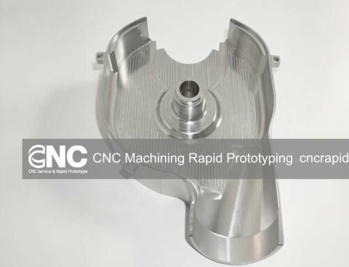
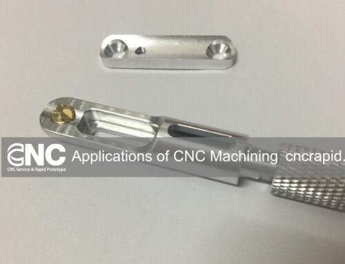
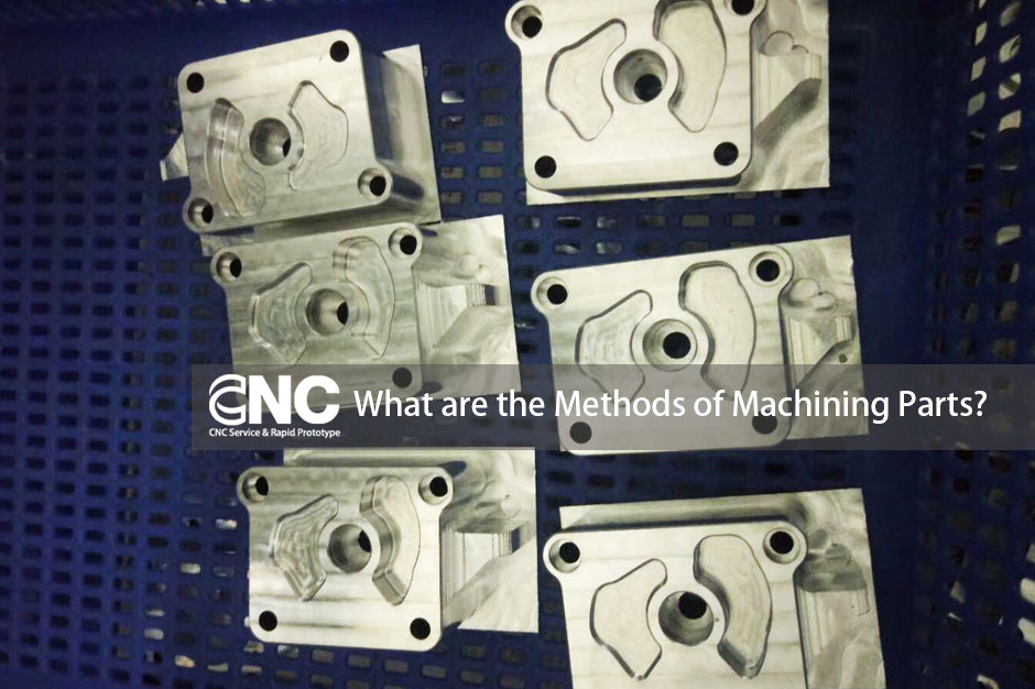
2. CNC Machining Services
Mechanical processing methods, which involve using machine tools to remove excess material from the blank, are employed to achieve the part’s shape. Depending on different machine movements and tools, various machining methods can be distinguished, including CNC turning, CNC milling, grinding, drilling, and boring.

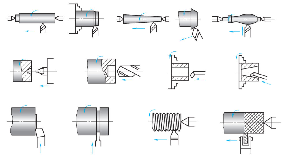
3. CNC Turning
CNC turning is characterized by the workpiece’s rotational movement, forming the primary cutting motion. The surface formed post-turning is mainly a rotary surface, but the workpiece’s end face can also be machined. Different workpiece shapes can be obtained through various feed movements of the tool relative to the workpiece.
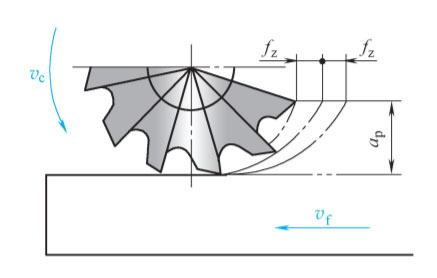
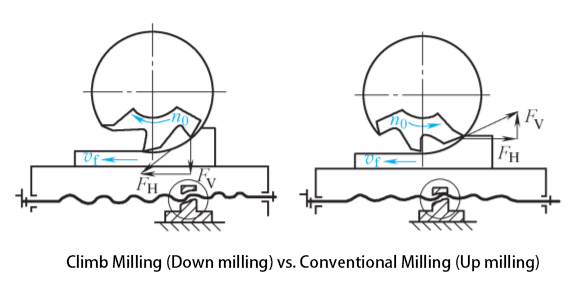
4. CNC Milling
In milling, the main cutting motion is the tool’s rotary motion, while the workpiece is fed through the machine tool’s table. Milling tools, often multi-edge tools, can be categorized into different methods, such as down milling and up milling, each with its own advantages and disadvantages.
5. Formative Manufacturing Technology
Formative manufacturing technology primarily involves mold forming, where the material’s quality remains essentially the same before and after forming, but only the shape changes. Molds can be divided into injection molds, die-casting molds, forging molds, stamping molds, blow molds, etc., and play a crucial role in manufacturing.
6. Additive Manufacturing Technologies
Additive manufacturing, or 3D printing, creates objects based on 3D CAD data, usually through a layer-by-layer process. This technology uses a wide range of materials, such as glass fibers, durable nylon materials, gypsum materials, aluminum alloys, titanium alloys, stainless steel, rubber-like materials, biomaterials, food materials, etc., and has become an effective technology to accelerate new product development.
The methods of machining parts, whether through CNC machining services, formative manufacturing technology, or additive manufacturing technologies, play a crucial role in the manufacturing process of modern mechanical products. By understanding and leveraging these methods, manufacturers can ensure the accurate and efficient production of complex parts across various applications and industries.
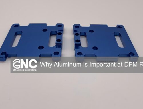
About DFM Rapid
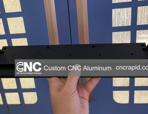
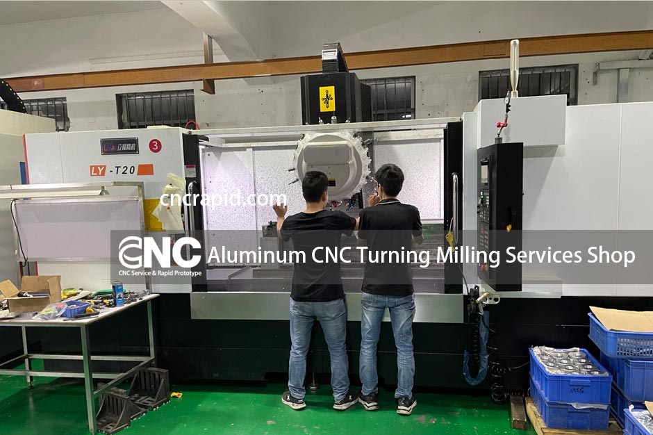
We are a CNC machining China shop in Dongguan. We have 20 CNC milling and turning machines in our shop. We can offer you CNC rapid prototyping and low-volume CNC machining services for plastic and metal parts. Also, surface finish like anodized, powder coating is available. If you need Metal & Plastic parts machined for prototypes or production, please feel free to get a quote online.
Or email us at [email protected] to tell us About Your Project
Please include the following information so that we can provide an accurate quote:
- Part Name
- 3D Drawing
- Quantity
- Material
- Tolerance Range
- Surface Finish
Thank you for your time!